Introduction
I find it very interesting, using the Adafruit Medium RGB Matrix Panel (16×32 Pixel) with the ESP32. Unfortunately, until now, the Adafruit libraries did not support the ESP32 for driving the Matrix Panel.
Therefore I started migrating the Adafruit RGB-Matrix-Panel library to support the ESP32 as well.
Hardware
At first I’ll look into the hardware connection between the ESP32 Development Kit and the RGB Matrix Panel. Adafruit describes the connection using jumper wires in their blog. Unfortunately, we cannot use this easy type of connection as the RGB matrices expect 5V I/O voltage and the ESP32 does only deliver 3.3V.
I’ve tested using 3.3V I/O Voltage to drive the RGB Matrix but it did not show the pictures clearly. For this reason, we will build an I/O level shifter board to connect the RGB Matrix and the ESP32 Development Board.
You can find very interesting hints on building prototype boards on arduino.fahrnet.de.
Level Shifter
To build the level shifter, we need the following materials.
BOM
| Part | Value | Device | Package | Description |
|---|---|---|---|---|
| D1 | 1N5817-B | 1N5817-B | DO41-7.6 | 1.0A SCHOTTKY BARRIER RECTIFIER |
| IC1 | 74AC244N | 74AC244N | DIL20 | Octal BUFFER and LINE DRIVER, 3-state |
| IC2 | 74AC244N | 74AC244N | DIL20 | Octal BUFFER and LINE DRIVER, 3-state |
| PCB1 | 25x15 points (full count) | PUNKTRASTER 254 | PUNKTRASTER | |
| SV1 | MA08-1 | MA08-1 | PIN HEADER | |
| SV2 | MA08-1 | MA08-1 | PIN HEADER | |
| SV3 | MA08-1 | MA08-1 | PIN HEADER | |
| SV4 | MA08-1 | MA08-1 | PIN HEADER | |
| SV5 | MA03-1 | MA03-1 | PIN HEADER | |
| X1 | BARREL_BKL_072752 | BARREL_BKL_072752 | BARREL_BKL_072752 | |
| X2 | MKDSN1,5/2-5,08 | MKDSN1,5/2-5,08 | MKDSN1,5/2-5,08 | MKDSN 1,5/ 2-5,08 Printklemme |
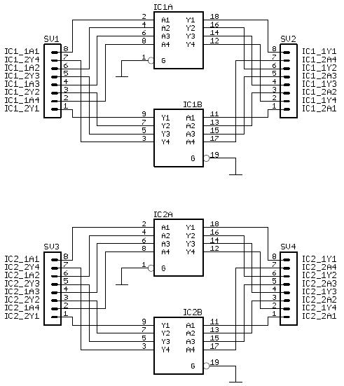
Schematic
The following picture shows the schematic for the level shifter board.
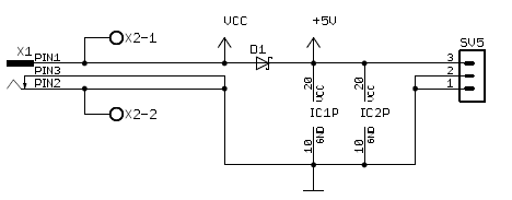
And additionally, we will use the board as power distribution unit for the matrix and the development board using the following schematic.
Board Layout
The Top Side Layout and Bottom Side Layout as PDFs to enable “print to scale”.
To make the soldering as easy as possible, we created a very lean board layout.
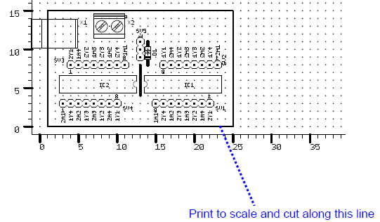
These two pictures show the top and bottom layout of the level shifter board. Even beginners should be able to correctly solder this board.

Board photographs
At first, we placed the components onto the board as shown in this picture and soldered one point to fix the components.

To make the connection easier, we bend the pins of the level shifter chips to the outside, so that we can directly solder them to the pin headers.
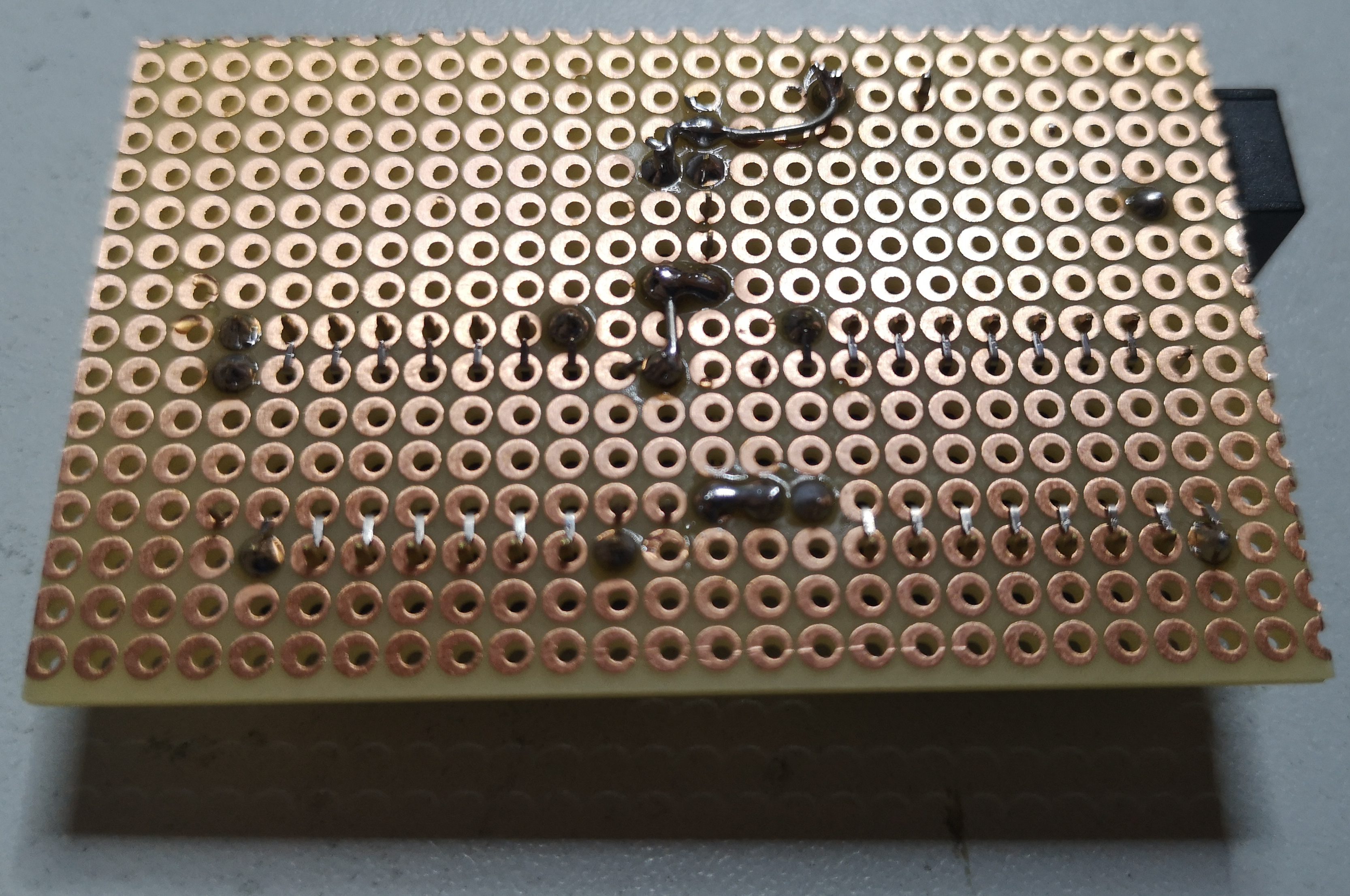
After that, we solder the pins together and finish with connecting the power leads using silver wire. At the end, it should look like in the following two pictures.
Finished


Connecting ESP32 and RGB Matrix using Level Shifter board
The following diagram shows the required connections between the ESP32 board, the level shifter board and the RGB Matrix Panel. Additionally, you need to connect the power cable of the Matrix panel to the screw terminals of the level shifter board and the barrel jack connector of the 5V power supply to the level shifter board.
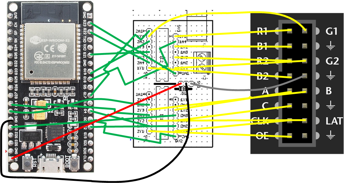
The following table shows the resulting pin to pin definitions.
| ESP32 GPIO | Level Shifter Input | Level Shifter Output | RGB Matrix Pin |
|---|---|---|---|
| 0 | IC1-2A1 | IC1-2Y1 | OE |
| 2 | IC1-2A2 | IC1-2Y2 | LAT |
| 4 | IC1-1A4 | IC1-1Y4 | CLK |
| 12 | IC1-1A2 | IC1-1Y2 | A |
| 13 | IC1-2A3 | IC1-2Y3 | B |
| 14 | IC1-1A3 | IC1-1Y3 | C |
| 17 | IC2-2A1 | IC2-2Y1 | R1 |
| 18 | IC2-1A4 | IC2-1Y4 | G1 |
| 19 | IC2-2A2 | IC2-2Y2 | B1 |
| 21 | IC2-2A3 | IC2-2Y3 | R2 |
| 22 | IC2-2A4 | IC2-2Y4 | G2 |
| 23 | IC2-1A1 | IC2-1Y1 | B2 |
| GND | GND | GND | GND |
Software
We use the Arduino IDE and the Adafruit RGB Matrix Panel Library to drive the Matrix Panel. The Adafruit GFX Library is used to easily draw graphics on the panel.
Install IDE
At first, we install the Arduino IDE on your computer. Please download the Arduino IDE and install it according to your operating system. Download from arduino.cc.
Install dependencies
We need a couple of libraries and the board support package to get started.
Arduino-ESP32
The easiest way to make your Arduino IDE compatible to the ESP32 is to use the board manager URL. Please copy the following URL:
https://dl.espressif.com/dl/package_esp32_index.json
Then open the Arduino IDE and go to “Preferences”. Then add the URL to the field “Additional Board Manager URLs”
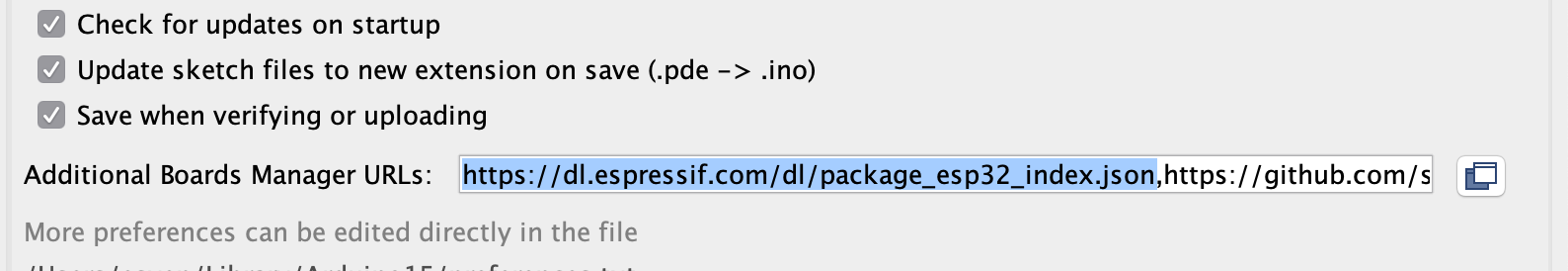
Next, click OK to close the Dialog.
Next, go to “Tools -> Board -> Boards Manager”. The Arduino IDE will not start to download the indexes from the board manager URLs and show the results to you.
Then search for “esp32” and install the resulting board support package by espressif.
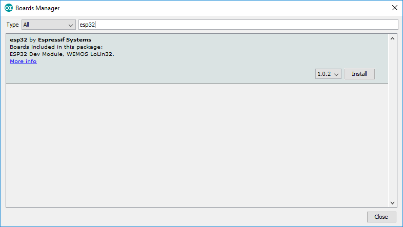
After clicking “Install”, the IDE will download the BSP including compilers and toolchain. This may take some time.
But after that, you are able to compile and run sketches on your ESP32 board.
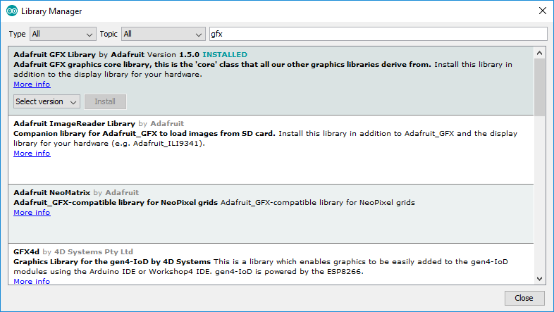
Adafruit GFX Library
Open the Library Manager from the Tools menu and search for the Adafruit GFX Library and click install.
Adafruit RGB Matrix Panel Library
Unfortunately, you cannot use the Library Manager to install the current version of this library that supports running the panel using the ESP32. Therefore we need to install the library manually using the current source code from GitHub.
Download the current source code as ZIP-file.
Extract the source into your Arduino-libraries folder in your documents folder.
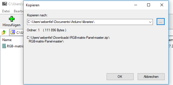
After extraction, you need to restart the Arduino IDE, if it is currently running.
Code Example
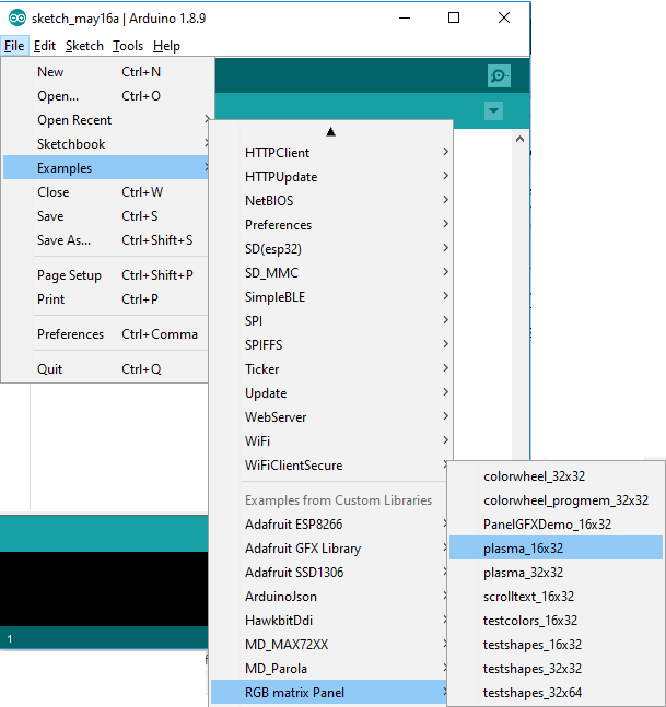
To test your installation and hardware, you can use the plasma_16x32 example from the RGB Matrix Panel Library.
Before you upload the code to your device, you need to change the code to use the following definitions.
#define CLK 8
#define OE 9
#define LAT 10
#define A A0
#define B A1
#define C A2

RGBmatrixPanel matrix(A, B, C, CLK, LAT, OE, true);
to
#define CLK 4
#define OE   0
#define LAT 2
#define A   12
#define B   13
#define C   14

const uint8_t rgbpins[] = { 17,18,19,21,22,23 };
RGBmatrixPanel *matrix = new RGBmatrixPanel(A, B, C, CLK, LAT, OE, true, (uint8_t *)rgbpins);
Now, compile the code and upload it to your ESP32 and have fun!
