Das Laden eines Elektroautos wie des Seat Mii Electric kann mit der richtigen Ausrüstung und einem durchdachten Setup nicht nur umweltfreundlich, sondern auch besonders kosteneffizient gestaltet werden. In diesem Beitrag möchte ich meine Erfahrungen und das Setup teilen, das es mir ermöglicht, meinen Elektro-PKW sehr günstig mit Solarstrom zu laden.
Unser PV-Anlagen-Setup
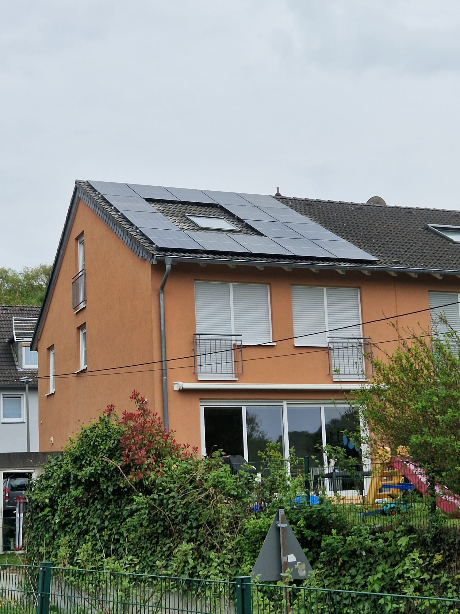
Unser Zuhause ist mit einer 13,4 kWp Photovoltaikanlage ausgestattet, die eine 50-50 Ost-West Ausrichtung besitzt. Diese ist mit einem 10 kW Huawei Sun2000 Wechselrichter verbunden. Da unser Haushalt auch eine Wärmepumpe nutzt, haben wir uns gegen einen Batteriespeicher entschieden. In unserem Fall würde sich ein Batteriespeicher aufgrund der intelligenten Stromverteilung über die Sonnenstunden erst sehr spät amortisieren, besonders da er in der Übergangs- und Winterzeit nicht vollständig geladen werden könnte.
Westseite der PV Anlage
Die Rolle der Heidelberg Energy Control Wallboxen
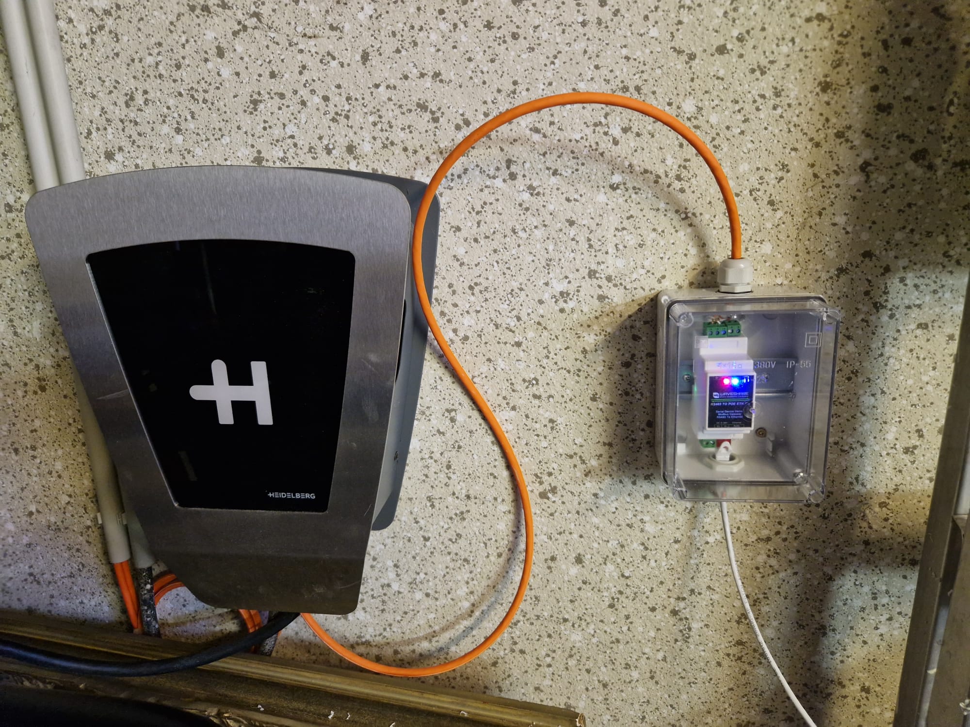
Zur optimalen Nutzung des Solarstroms für das Laden des Elektroautos kommen Wallboxen vom Typ Heidelberg Energy Control zum Einsatz. Diese Wallboxen lassen sich über Modbus RTU steuern, wodurch der Ladestrom innerhalb der gesetzlich vorgegebenen Grenzen von 6A bis 16A angepasst werden kann. Bei einem 3-phasigen Anschluss variiert die Ladeleistung zwischen 4,1 kW und 11 kW. Da der Seat Mii Electric jedoch nur 2-phasig laden kann, passt die Ladeleistung von 2,7 kW bis 7,2 kW perfekt in das Leistungsspektrum unserer PV-Anlage.
Anbindung an EVCC
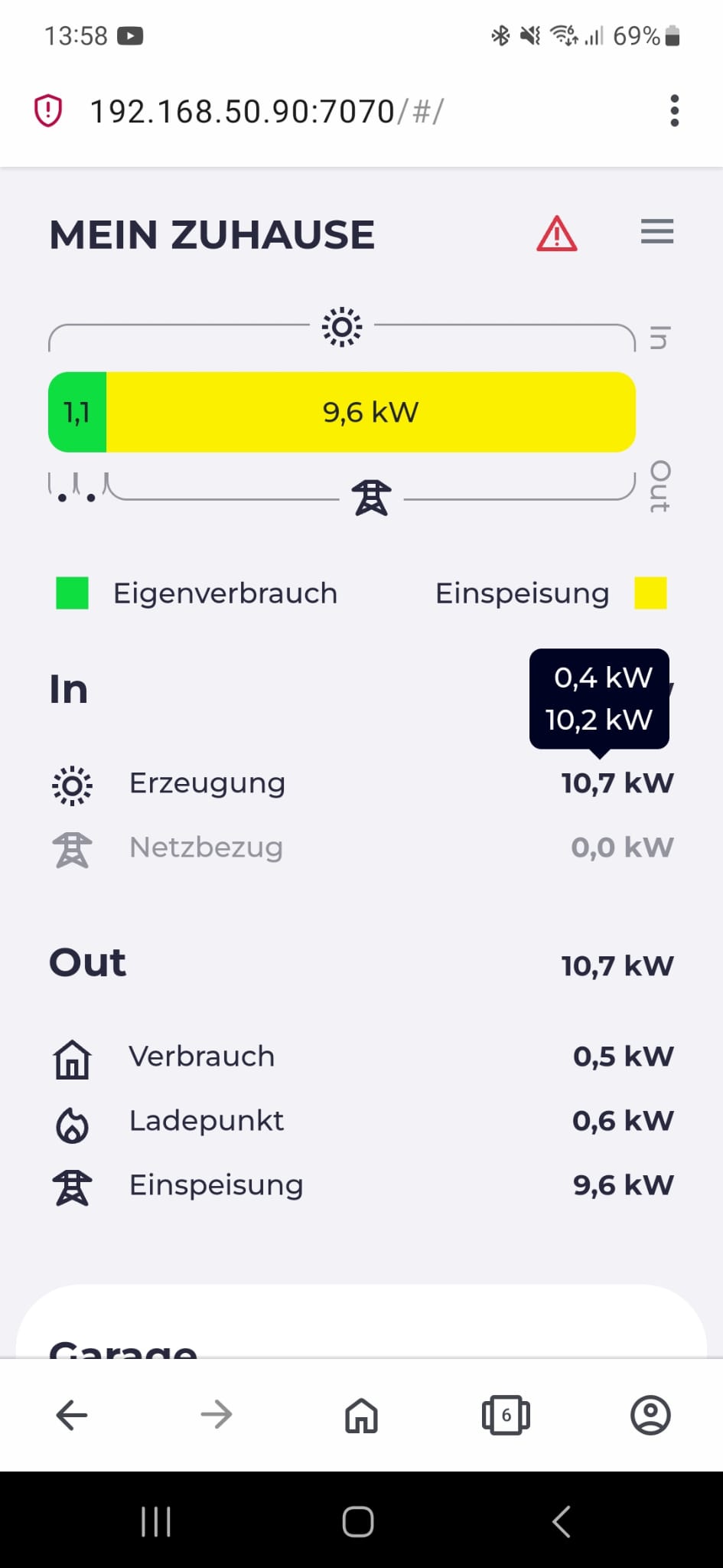
Die Integration der PV-Anlage in EVCC erfolgt über einen Smart Dongle WLAN-FE mit ModbusTCP-Schnittstelle. Ein wichtiger Hinweis hierbei ist, dass die Schnittstelle erst in den Geräteeinstellungen der App aktiviert werden muss. Zur Ermittlung des Netzeinspeisungsüberschusses verwenden wir ein Smart Meter, z.B. das Modell DTSU666-H.
EVCC
Für die Wallbox-Anbindung nutzen wir einen RS485 TO POE ETH Signalwandler von Waveshare, der dank Power over Ethernet (PoE) eine einfache und galvanisch getrennte Versorgung über unser Netzwerk ermöglicht. Den Signalwandler könnt ihr oben neben der Wallbox sehen.
Effizienz und Kosteneinsparungen
Durch dieses Setup konnten wir bereits erhebliche Kosteneinsparungen erzielen. Im September 2023 beispielsweise luden wir etwa 216 kWh zu 91,6 % direkt aus der Sonnenenergie. Mit einer entgangenen Einspeisevergütung von etwa 7 Cent pro kWh kostete uns dieser Strom lediglich 20,63 Euro. Das entspricht ungefähr 1,15 Euro pro 100 km, womit wir allein in diesem Monat rund 60 Euro einsparen konnten.
Fazit
Der anfängliche Aufwand für die Einrichtung eines solchen Systems mag zwar beträchtlich sein, die daraus resultierenden Kosteneinsparungen und der Beitrag zum Umweltschutz rechtfertigen jedoch diese Investition. Durch die intelligente Nutzung von Solarstrom zum Laden unseres Elektroautos können wir die Betriebskosten erheblich senken und gleichzeitig unsere CO2-Bilanz verbessern. Dieses Setup ist ein hervorragendes Beispiel dafür, wie technologische Innovationen und umweltfreundliche Praktiken Hand in Hand gehen können, um eine nachhaltigere Zukunft zu fördern.
Als begeisterter Nutzer von Elektrofahrzeugen war ich gespannt auf meine Erfahrungen mit dem Seat Mii Electric Edition PowerCharge. Dieses Auto hat mich in vielerlei Hinsicht beeindruckt, sowohl positiv als auch mit einigen Einschränkungen, die es zu beachten gilt. Hier teile ich meine Erfahrungen, um anderen potenziellen Käufern einen Einblick in die Vor- und Nachteile dieses speziellen Elektroautos zu geben.
Seat Mii electric
Positiverlebnisse mit dem Seat Mii Electric
Effizienz und Reichweite
Eines der herausragendsten Merkmale des Seat Mii Electric ist seine Effizienz. Mit einem Verbrauch von etwa 12 bis 14 kWh auf 100 km gehört er zu den sparsamsten Elektroautos auf dem Markt. Dies, gepaart mit einem 36 kWh Akku, verspricht eine ausreichende Reichweite für den täglichen Bedarf, was ihn zu einem idealen Alltagsauto macht.
Nützliche App-Funktionen
Die zugehörige App des Seat Mii Electric bietet alle notwendigen Funktionen, die man von einem modernen Elektroauto erwarten würde:
Ladestandskontrolle und Einstellung von Ladegrenzen: Diese Funktion ermöglicht eine effiziente Planung der Ladevorgänge und hilft, den Akku zu schonen.
Kontrolle über die Ladegeschwindigkeit: Besonders nützlich, wenn man über Nacht lädt oder einfach Zeit spart, indem man die Geschwindigkeit anpasst.
Zuverlässige Aktivierung der Standheizung: Für kalte Tage ein Segen, lässt sich das Auto vorwärmen, ohne in das kalte Auto einsteigen zu müssen.
Zusätzlich bietet die kompakte Größe des Fahrzeugs den Vorteil, fast überall einen Parkplatz zu finden, was in der Stadt ein unschätzbarer Vorteil ist.
Schnellladung und Agilität
Mit einem CCS-Ladestecker ausgestattet, kann der Akku des Seat Mii Electric auch auf längeren Strecken zügig aufgeladen werden, was die Flexibilität erheblich erhöht. Seine Agilität macht ihn zu einem hervorragenden Stadtauto, mit genügend Leistung für gelegentliches Überholen auf der Autobahn.
Herausforderungen und Einschränkungen
Größe und Komfort
Für Familien mit zwei Kindern könnte die Größe des Seat Mii Electric eine Herausforderung darstellen. Es ist klar, dass dieses Fahrzeug nicht auf Dauer für größere Familien geeignet ist. Ebenso lässt der Komfort auf längeren Strecken zu wünschen übrig, was bei längeren Fahrten bedacht werden sollte.
Geschwindigkeitsbegrenzungen
Obwohl der Seat Mii Electric für das Überholen auf der Autobahn ausreichend ist, kann seine Höchstgeschwindigkeit von etwa 130 km/h in manchen Situationen limitierend wirken.
Fazit
Der Seat Mii Electric Edition PowerCharge ist ein beeindruckendes Elektroauto mit vielen Vorteilen für den täglichen Gebrauch, besonders in urbanen Gebieten. Seine Effizienz, praktische App-Funktionen und Schnellladefähigkeit machen ihn zu einer attraktiven Option für viele. Dennoch sollten potenzielle Käufer die Größen- und Komforteinschränkungen im Auge behalten, besonders wenn sie planen, das Fahrzeug als Hauptauto für eine Familie zu nutzen. Trotz dieser Einschränkungen bietet der Seat Mii Electric eine solide Leistung und bestätigt den Wert von Elektrofahrzeugen im Alltag.
When I tried to use my ESP32 Development Kit ordered by AZ-Delivery on my Macbook Pro 2017, it did not work. The macOS did not show the serial port of the DevKit.
Searching Google for this issue indicates that I am not the only one having this problem.
I’ve found the following articles talking about this issue:
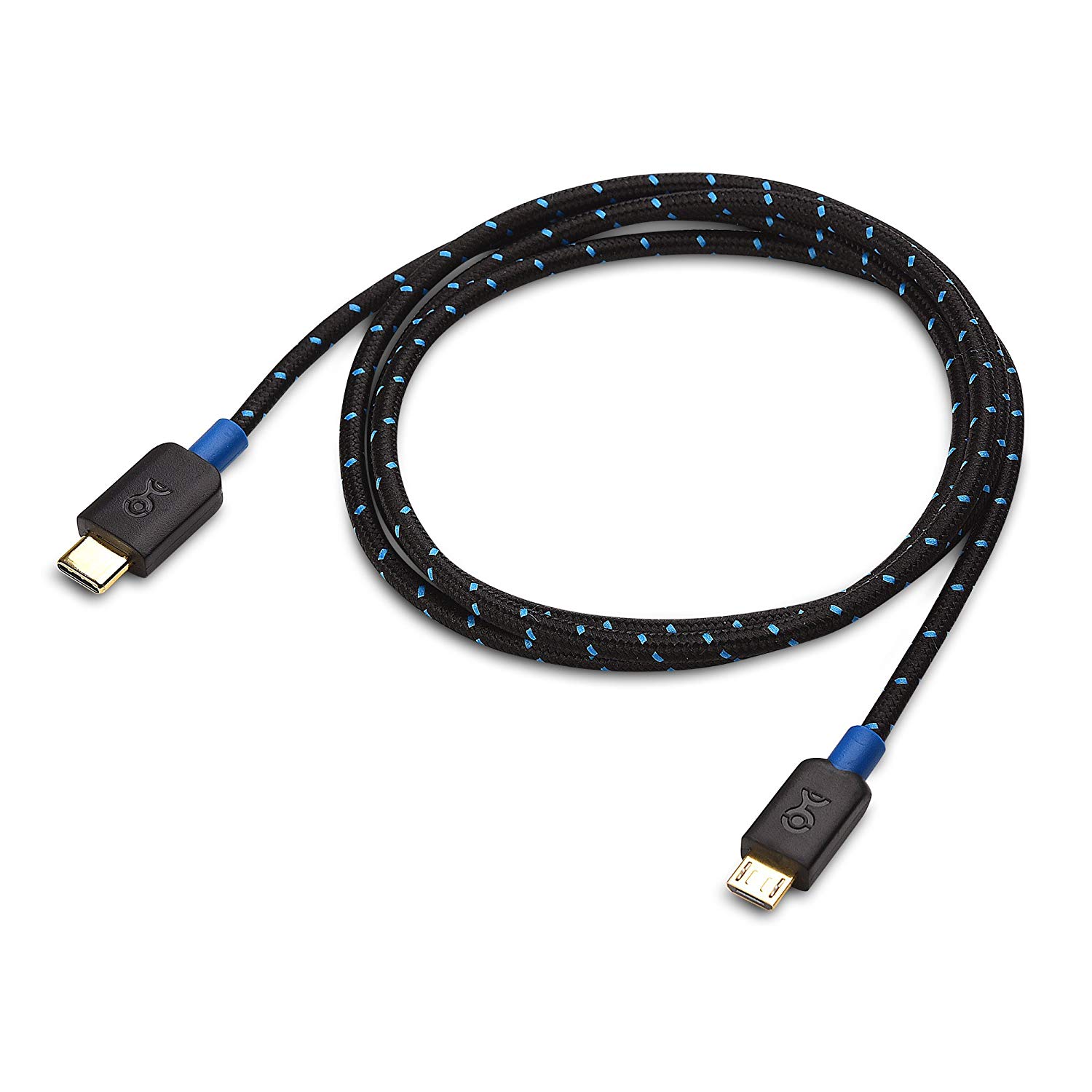
Cable Matters® USB 2.0 Micro-B Kabel A Type C (USB-C)
Any other USB-C to USB-A adapter with another USB-A to Micro-USB cable did not work for me.
There is just one other device I found that made it working with the Macbook as well.
I find it very interesting, using the Adafruit Medium RGB Matrix Panel (16×32 Pixel) with the ESP32. Unfortunately, until now, the Adafruit libraries did not support the ESP32 for driving the Matrix Panel.
Therefore I started migrating the Adafruit RGB-Matrix-Panel library to support the ESP32 as well.
Hardware
At first I’ll look into the hardware connection between the ESP32 Development Kit and the RGB Matrix Panel. Adafruit describes the connection using jumper wires in their blog. Unfortunately, we cannot use this easy type of connection as the RGB matrices expect 5V I/O voltage and the ESP32 does only deliver 3.3V.
I’ve tested using 3.3V I/O Voltage to drive the RGB Matrix but it did not show the pictures clearly. For this reason, we will build an I/O level shifter board to connect the RGB Matrix and the ESP32 Development Board.
You can find very interesting hints on building prototype boards on arduino.fahrnet.de.
Level Shifter
To build the level shifter, we need the following materials.
BOM
Part
Value
Device
Package
Description
D1
1N5817-B
1N5817-B
DO41-7.6
1.0A SCHOTTKY BARRIER RECTIFIER
IC1
74AC244N
74AC244N
DIL20
Octal BUFFER and LINE DRIVER, 3-state
IC2
74AC244N
74AC244N
DIL20
Octal BUFFER and LINE DRIVER, 3-state
PCB1
25x15 points (full count)
PUNKTRASTER 254
PUNKTRASTER
SV1
MA08-1
MA08-1
PIN HEADER
SV2
MA08-1
MA08-1
PIN HEADER
SV3
MA08-1
MA08-1
PIN HEADER
SV4
MA08-1
MA08-1
PIN HEADER
SV5
MA03-1
MA03-1
PIN HEADER
X1
BARREL_BKL_072752
BARREL_BKL_072752
BARREL_BKL_072752
X2
MKDSN1,5/2-5,08
MKDSN1,5/2-5,08
MKDSN1,5/2-5,08
MKDSN 1,5/ 2-5,08 Printklemme
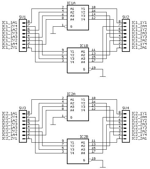
Schematic
The following picture shows the schematic for the level shifter board.
Schematic Level Shifter
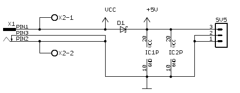
And additionally, we will use the board as power distribution unit for the matrix and the development board using the following schematic.
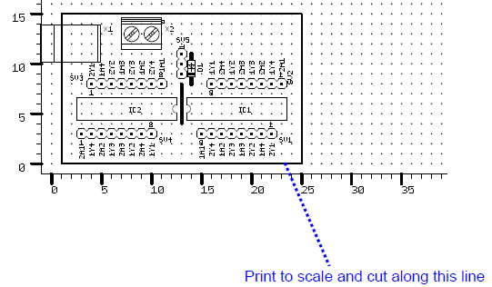
To make the soldering as easy as possible, we created a very lean board layout.
Top side layout level shifter
These two pictures show the top and bottom layout of the level shifter board. Even beginners should be able to correctly solder this board.
level-shifter-board-bottom-layout
Board photographs
At first, we placed the components onto the board as shown in this picture and soldered one point to fix the components.
Level shifter board top side component placement
To make the connection easier, we bend the pins of the level shifter chips to the outside, so that we can directly solder them to the pin headers.
Establish contact before soldering
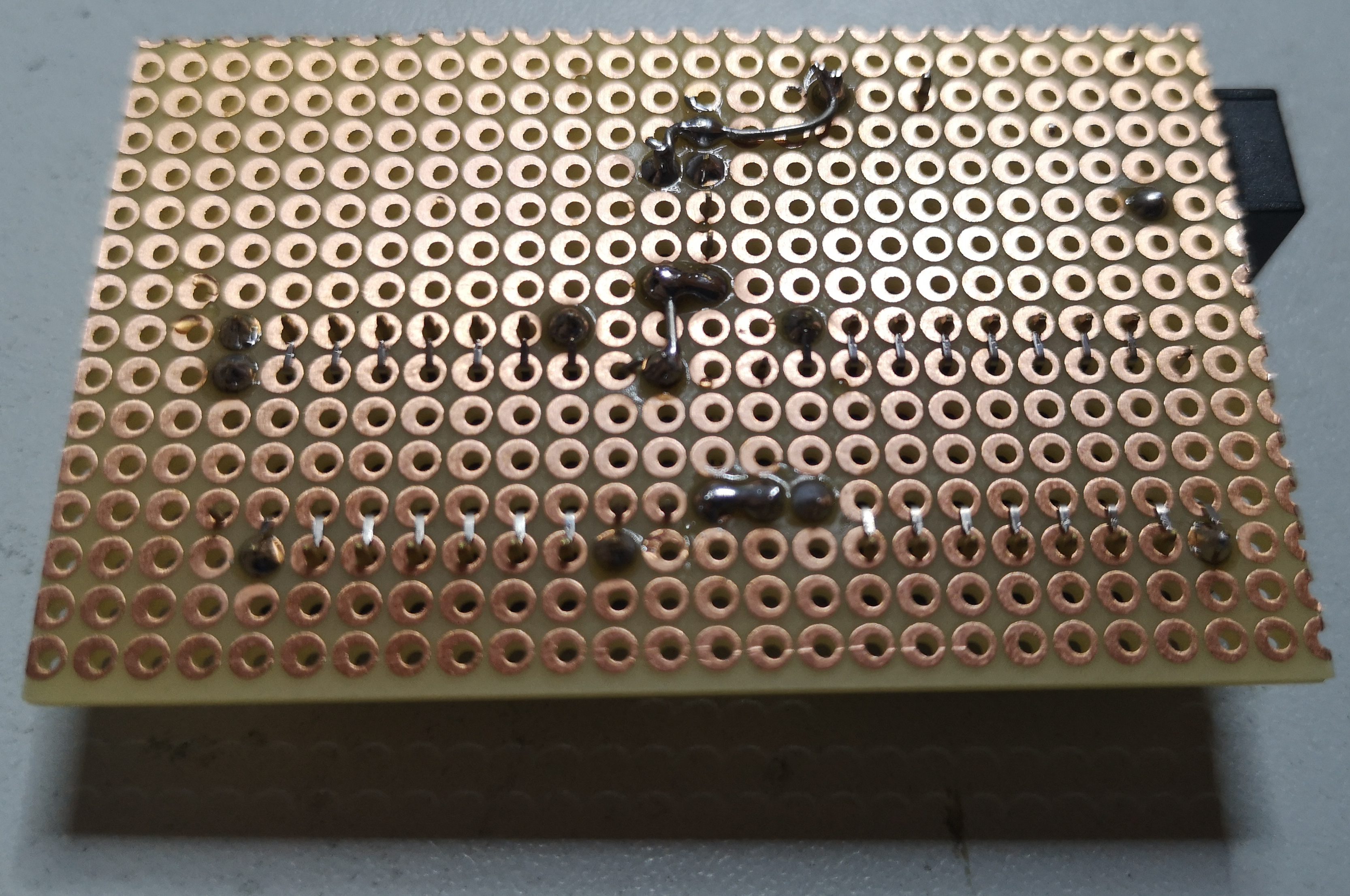
After that, we solder the pins together and finish with connecting the power leads using silver wire. At the end, it should look like in the following two pictures.
Finished
Finished level shifter board top side
Finished level shifter board bottom side
Connecting ESP32 and RGB Matrix using Level Shifter board
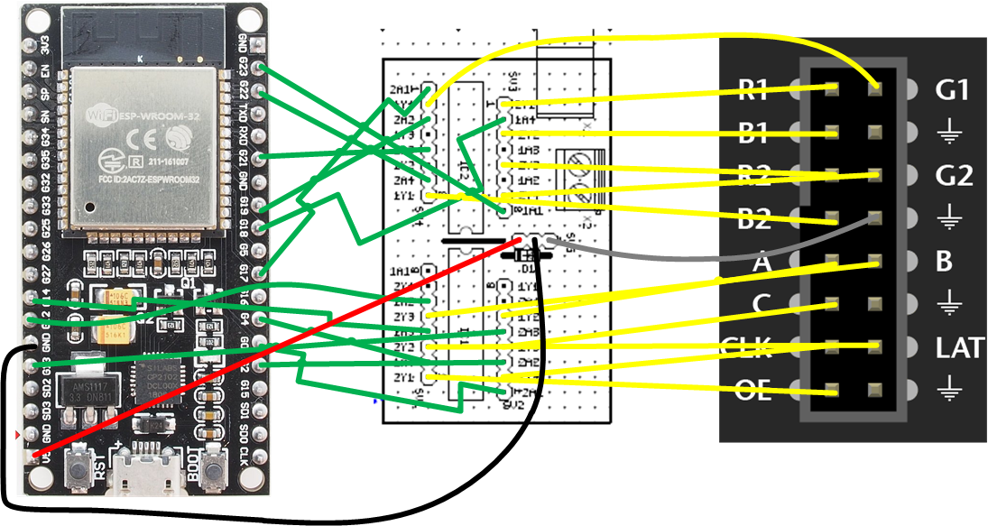
The following diagram shows the required connections between the ESP32 board, the level shifter board and the RGB Matrix Panel. Additionally, you need to connect the power cable of the Matrix panel to the screw terminals of the level shifter board and the barrel jack connector of the 5V power supply to the level shifter board.
Matrix Panel Wiring Diagram
The following table shows the resulting pin to pin definitions.
ESP32 GPIO
Level Shifter Input
Level Shifter Output
RGB Matrix Pin
0
IC1-2A1
IC1-2Y1
OE
2
IC1-2A2
IC1-2Y2
LAT
4
IC1-1A4
IC1-1Y4
CLK
12
IC1-1A2
IC1-1Y2
A
13
IC1-2A3
IC1-2Y3
B
14
IC1-1A3
IC1-1Y3
C
17
IC2-2A1
IC2-2Y1
R1
18
IC2-1A4
IC2-1Y4
G1
19
IC2-2A2
IC2-2Y2
B1
21
IC2-2A3
IC2-2Y3
R2
22
IC2-2A4
IC2-2Y4
G2
23
IC2-1A1
IC2-1Y1
B2
GND
GND
GND
GND
Software
We use the Arduino IDE and the Adafruit RGB Matrix Panel Library to drive the Matrix Panel. The Adafruit GFX Library is used to easily draw graphics on the panel.
Install IDE
At first, we install the Arduino IDE on your computer. Please download the Arduino IDE and install it according to your operating system. Download from arduino.cc.
Install dependencies
We need a couple of libraries and the board support package to get started.
Arduino-ESP32
The easiest way to make your Arduino IDE compatible to the ESP32 is to use the board manager URL. Please copy the following URL:
Then open the Arduino IDE and go to “Preferences”. Then add the URL to the field “Additional Board Manager URLs”
Board Manager Setting
Next, click OK to close the Dialog.
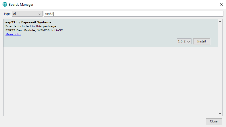
Next, go to “Tools -> Board -> Boards Manager”. The Arduino IDE will not start to download the indexes from the board manager URLs and show the results to you.
Then search for “esp32” and install the resulting board support package by espressif.
ESP32 Board Manager
After clicking “Install”, the IDE will download the BSP including compilers and toolchain. This may take some time.
But after that, you are able to compile and run sketches on your ESP32 board.
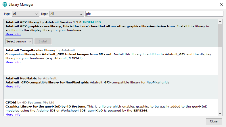
Adafruit GFX Library
Open the Library Manager from the Tools menu and search for the Adafruit GFX Library and click install.
Adafruit RGB Matrix Panel Library
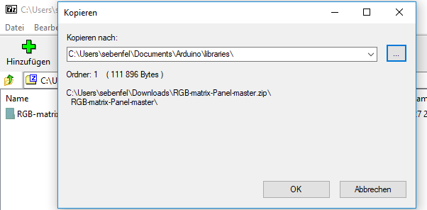
Unfortunately, you cannot use the Library Manager to install the current version of this library that supports running the panel using the ESP32. Therefore we need to install the library manually using the current source code from GitHub.